I got interested in neon ring counters after seeing PA3FWM’s incredible Nixie-clock using neon lamps as logic elements. Quickly I discovered Ronald Dekker’s comprehensive Ring Counter Variations page. It lead me to an old book, “Electronic Counting Circuits” by J.B. Dance available from Dieter’s Nixie World (zipped PDF document). I highly recommend taking a read of all these sources.
What I found captivating about these devices was that each neon bulb had a dual function. Not only does each bulb indicate the count but it also stores the state of the count. Each neon acts as a memory device, holding its state until the next pulse arrives. With a handful of neon bulbs it is therefore possible to create a counter or a divider. And the only other parts required are some readily obtained resistors, diodes and capacitors. No transistors, no integrated circuits, no other tubes. Just neon bulbs.
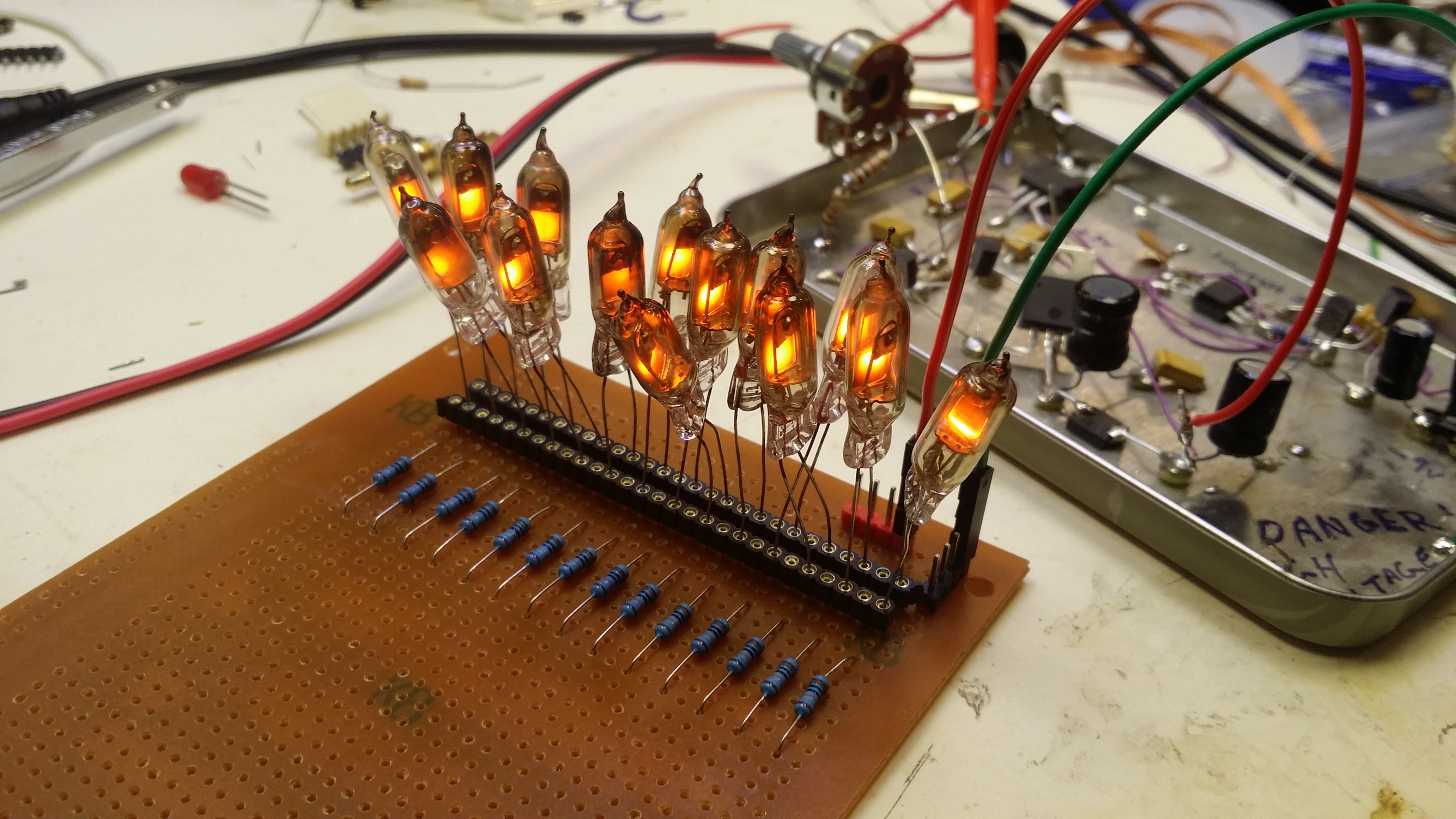
Enchanted by the simplicity of all of this, I just had to give making a neon ring counter a go; here is the result:
Characterising Neons
To begin I ordered 200 Russian IN-3 bulbs. These were made in the same factories that made Russian nixie tubes until the collapse of the USSR. Mine came from an ebay seller in the Ukraine as new-old-stock (NOS) in the original cardboard boxes. Each bulb is built of the same components, but visually there is quite a lot of variation from one bulb to the next. Some have a darker, sootier appearance to the glass. Some have a slightly larger volume than the others. And some have the anodes and cathodes positioned higher or lower within the glass envelope. When lit, some have a stable glow, while some have a tendency to “wink”! Some look blurry and some glow in the wrong places, while most present the intended sharp squarish dot of orange glow. Clearly there is quite a lot of variation from tube to tube. Far more than what one might observe in a batch of modern, “Western-style” neons. One could view this as endearing or frustrating or both at the same time.
From Roland Dekker’s page I garnered the importance of selecting neons with similar characteristics when making a ring counter. The salient characteristics are “striking voltage” and “maintaining voltage”. The “striking voltage” is the voltage that must be supplied to the tube to make the gas initially ionise. Once the bulb has “struck”, it will maintain its glow as long as the voltage remains above the “maintaining voltage”. The maintaining voltage is always lower than the striking voltage and the difference between the two can be significant (like tens of volts).
I decided to characterise 50 out of the 200 bulbs, so I’d get a good sense of the spread of striking and maintaining voltages. I made a test fixture using a high voltage power supply with an adjustment range from ~65 volts to 105 volts (I took a gamble that the striking voltage of all the neons would fall within this range), 2 voltmeters, a series resistor, and some sockets to hold a neon tube.
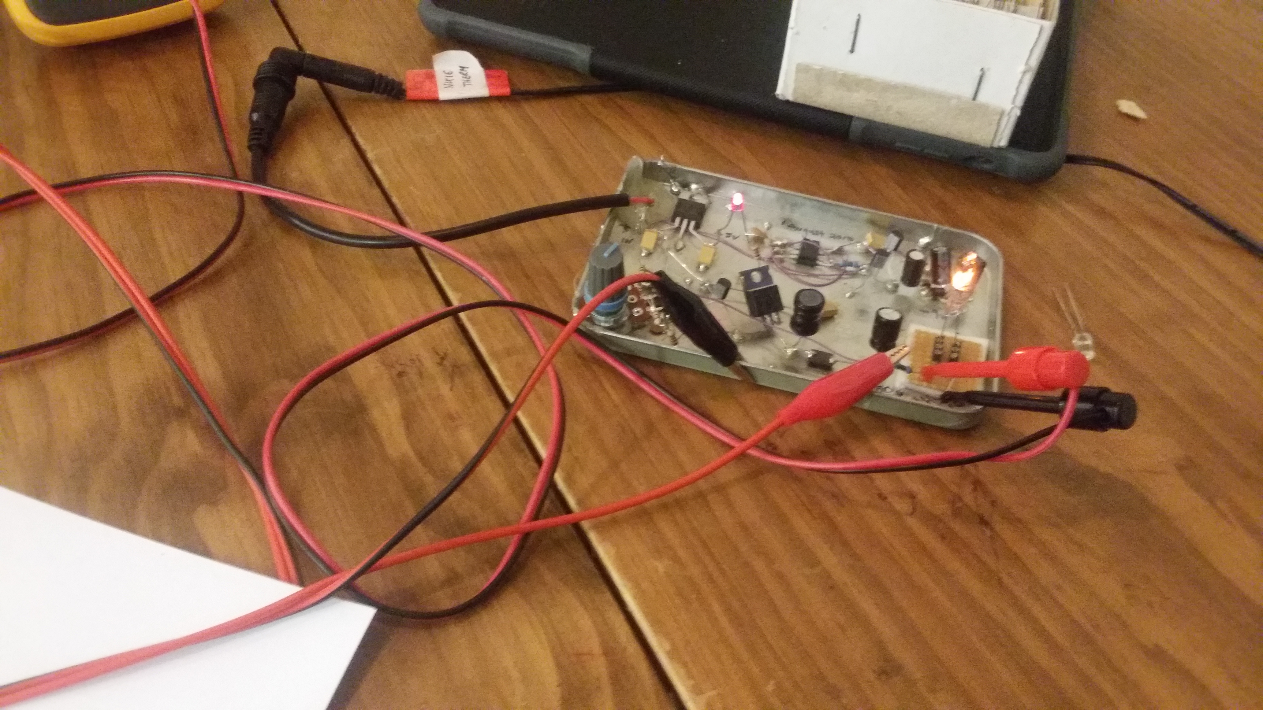
One voltmeter measured the supply voltage, while the other measured the voltage across the neon. The test procedure was:
- Set high voltage power supply to lowest setting (65 volts).
- Connect neon tube to be tested.
- Switch on the high voltage power supply. The neon should be extinguished since the supply voltage is below the striking voltage.
- Slowly adjust power supply until neon just starts to glow.
- Read off the power supply voltage. I took this to be the striking voltage.
- Read off the voltage across the neon. I took this to be the maintaining voltage.
- Record each reading on a spreadsheet.
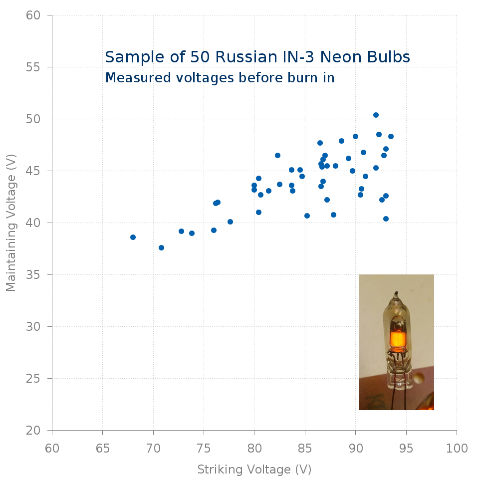
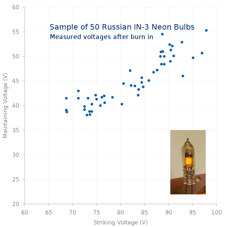
I carefully labelled my neons so I could link physical neons to recorded measurements. Using gnuplot is was able to plot the spread of striking and maintaining voltages for the 50 bulbs. The variation from bulb to bulb was quite pronounced:
Burn in
A number of sources suggested that the characteristics of “fresh” neon bulbs differ quite markedly to when they have been in service for some time. Apparently after a couple of days they “settle down” and thereafter the striking and maintaining voltages don’t move around too much. So I built a fixture to subject my neon bulbs to 48 hours burn in. My set up consisted of a high voltage power supply (set to about 150V), 14 series resistors, and 14 sockets to attach neons. With this fixture I was able to burn in 14 neons simultaneously. Consequently, to process all 50 neons took 8 days.
After patiently waiting and swapping neons in and out of the fixture, I repeated the process of recording the striking and maintaining voltage of each neon, as described abpve. Here is a plot of the spread of values now:
Clearly the characteristics of the bulbs have changed. Since I had before and after data for each bulb, I was also able to visualise the change in each bulb’s characteristics as a result of the 48 hour burn in:
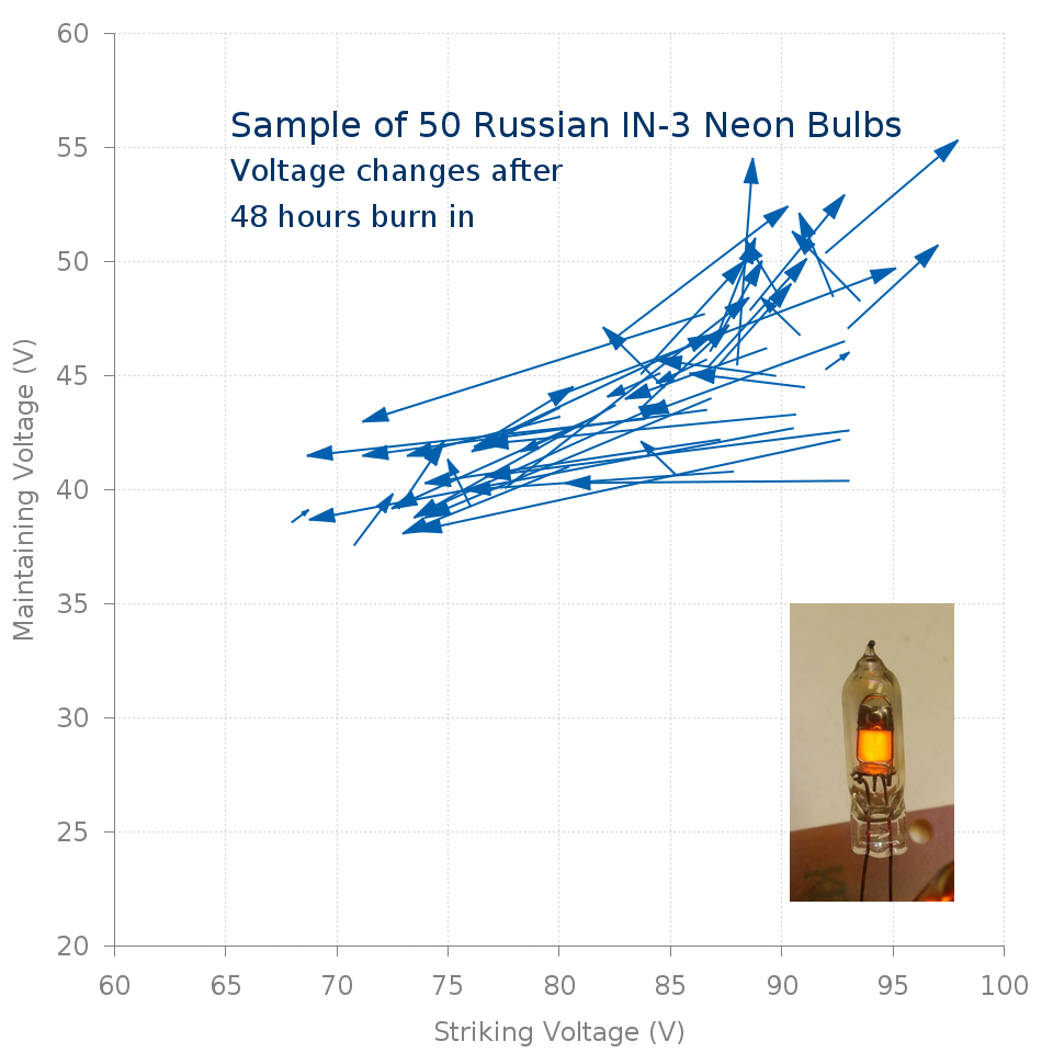
Some neons underwent substantial changes, particularly in terms of striking voltage. Interestingly there wasn’t a uniform increase or reduction in voltages after burn in. As can be seen the arrows linking a neon’s before and after voltages shoot off in all directions and gradients.
With all the data at hand it is possible to make a selection of well-matched neons. For this, I regenerated the plot of the measured characteristics after 48 hours burn in, this time with each neon labelled. By visual inspection I identified three clusters of neons with strike and maintaining voltages within a tight range:
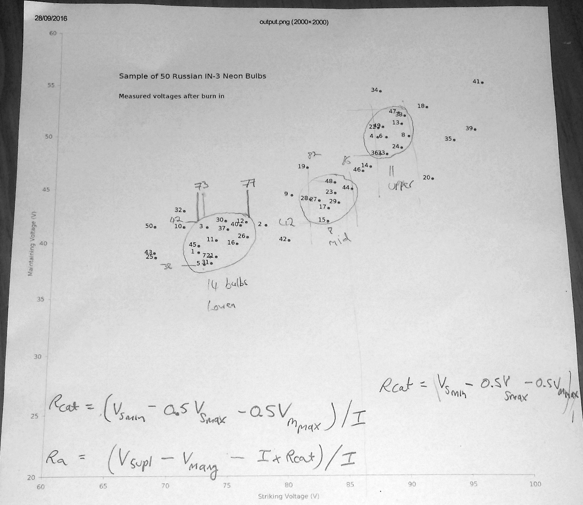
I labelled each cluster “Lower”, “Middle” and “Upper” and recorded the approximate striking and maintaining voltage ranges for neons in each cluster:
- Lower (14 bulbs)
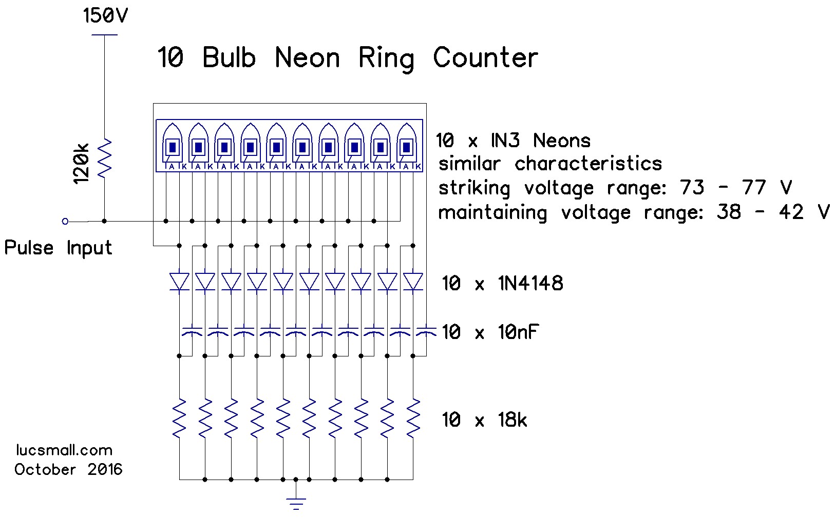
- Striking voltage range: 73 - 77 V
- Maintaining voltage range: 38 - 42 V
- Middle (8 bulbs)
- Striking voltage range: 82 - 86 V
- Maintaining voltage range: 42 - 46 V
- Upper (11 bulbs)
- Striking voltage range: 88 - 92 V
- Maintaining voltage range: 48 - 53 V
Designing the ring counter
Two parts of the ring counter circuit are affected by the striking and maintaining voltages of the matched neons. These are the cathode resistor (of which there is one per neon) and the anode resistor (of which there is one per ring counter). The values of these resistors are also affected by the supply voltage and the desired current through the neons. On his page, Roland Dekker presents formulas to determine the value of the cathode and anode resistors, with a lot of valuable details about their derivation. I mechanically applied these formulas to determine the “ideal” resistor values for the “Lower” cluster neons, a supply voltage of 150 volts, and a neon current of 800 micro Amps. I then rounded these to the nearest practical resistor values.
Here are the inputs to the formulas:
- Ineon = 800uA (target current through neon, typically 800uA to 1mA)
- Vsupply = 150V (supply voltage of high voltage power supply)
- Vstrike,min = 73V (minimum striking voltage of matched neons)
- Vstrike,max = 77V (maximum striking voltage of matched neons)
- Vmaint,max = 42V (maximum maintaining voltage of matched neons)
- Vmaint,avg = 40V (average maintaining voltage of matched neons)
For the last value, Vmaint,avg, I took the mid-point between the maximum maintaining voltage (42V) and the minimum maintaining voltage (38V), giving a value of 40 volts.
With these values, I calculated Rcathode:
Rcathode = (Vstrike,min - (0.5 * Vstrike,max) - (0.5 * Vmaint,max)) / Ineon
         = (73 - (0.5 * 77) - (0.5 * 42) / (800 * 10^-06)
         = 13.5 / (800 * 10^-06)
         = 16875 ohms
use 18k resistor
And the value for Ranode:
Ranode = (Vsupply - Vmaint,avg - (Ineon * Rcathode)) / Ineon
       = (150 - 40 - 13.5) / (800 * 10^-06)
       = 96.5 / (800 * 10^-06)
       = 120625 ohms
use 120k resistor
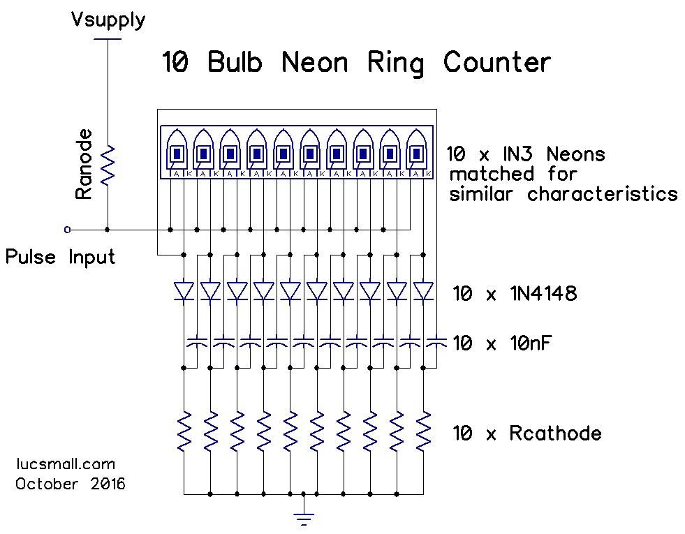
This resulted in a circuit as follows:
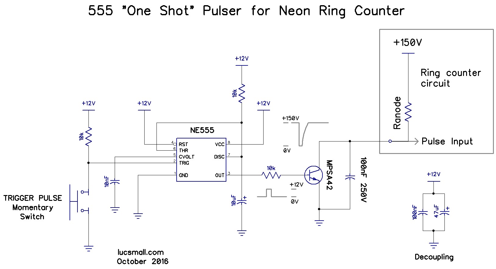
“One-shot” Pulsing circuit
Next I designed a circuit to generate pulses to advance the counter. For this I used a 555 timer configured as a monostable. For each button press, the 555 generates a clean ~110 millisecond output pulse. The output of the 555 drives an MPSA42 high voltage NPN transistor which pulls the neon anodes low to advance the count. Following Ronald Decker’s advice, I added a 100nF 250V DC capacitor across the transistor (he used 27nF, but 100nF is what I had on hand).
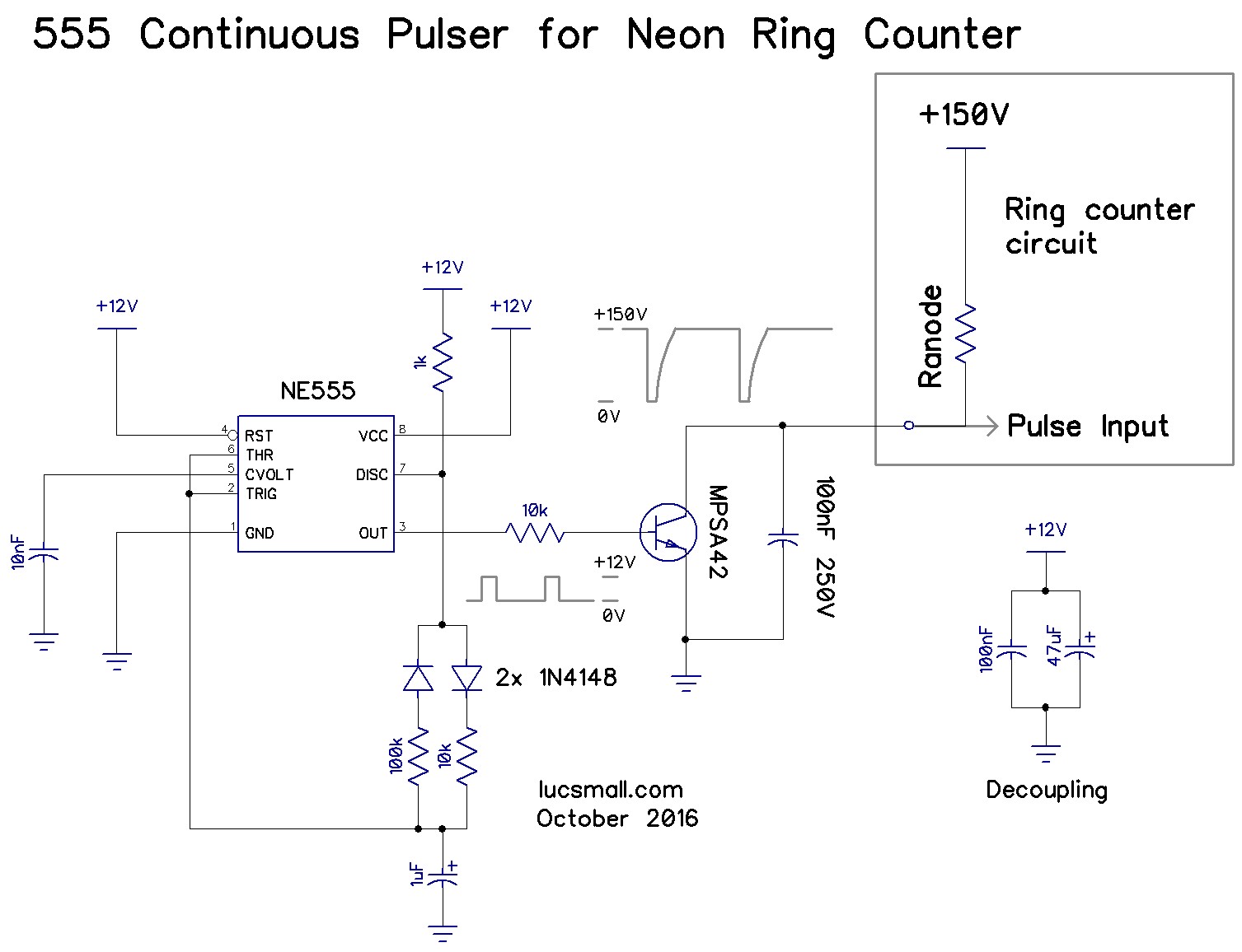
Continuous Pulsing Circuit
I soon tired of pressing a button to advance the counter, so I designed this continuous pulsing circuit, using a 555 timer configured in astable mode.
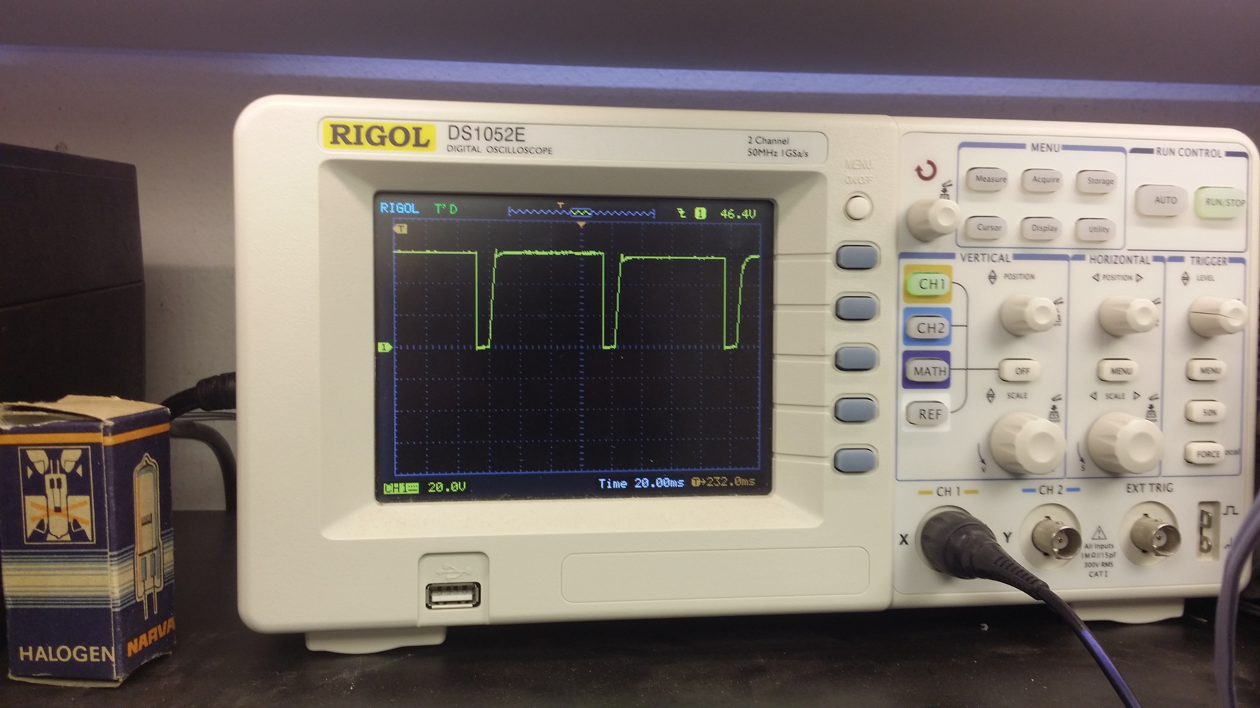
Based on the scope trace it pulses around 12.5Hz give or take:
Conclusion
Making a working neon ring counter was a really interesting exercise. I learned a heck of a lot about neons in the process. Taking the extra effort to characterise the bulbs and select well-matched ones was a strategy which paid off when the counter worked first time!
I’d now like to build more ring counters and chain them to create a clock a bit like the one that initially captured my interest.
Now I’m clear on the methodology for doing that:
- Burn in neons for ~2 days.
- Measure striking and maintaining voltage for each neon.
- Divide into closely-matched groups based on these characteristics.
- Calculate cathode and anode resistors for the group.
- Build the ring counter.