lucsmall.com

Hacking the WH2 Wireless Weather Station Outdoor Sensor – Part 2: Protocol Specification

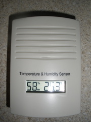
In Part 1 of this series of posts, I described the process of reverse engineering the WH2 outdoor weather sensor from Fine Offset Electronics. Here’s what the sensor looks like:

The WH2 wireless outdoor sensor transmits on 433.92MHz - sometimes known as the 433MHz or 434MHz band - using On-Off Keying. In normal operation (after a start up period during which the receiving indoor unit attempts to discover the remote sensor(s)) the WH2 transmits a data packet every 48 seconds, as depicted below:

From now on, I’ll refer to these data bursts as packets.
Hacking the WH2 Wireless Weather Station Outdoor Sensor - Part 1: Reverse Engineering the Protocol

I was interested in doing some datalogging of weather conditions around my house. Some kind of wireless sensor network is obviously attractive for this purpose given that there’s no cabling to be done. Rather than rolling my own protocol and making my own sensors, I thought I’d see if I could reverse engineer the packets from an existing outdoor sensor.

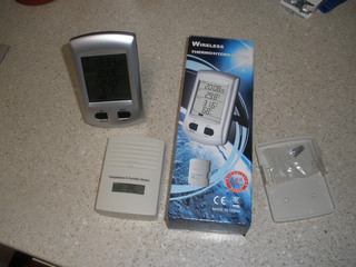
I’ve had a wireless weather station that used a WH2 outdoor weather sensor for a few years now. A bit of googling revealed that these are made by Fine Offset Electronics. The remote sensor measures both temperature and humidity. They interface to several different kinds of indoor weather stations produced by Fine Offset. One such unit, catalogue number X7020,  is sold by Altronics here in Australia. There are plenty of similar units listed on ebay. The unit from Altronics is shown below:

Open 7400 Logic Competition: I Won a Prize!

I awoke one morning recently to check my email and find out that I was a prize winner in the Open 7400 competition. I came equal third, a result shared with 21 others. There were some very fine entries in this competition and some very fine prizes to match. An interesting facet of being a prize-winner in this competition was that I could choose the prize I wanted.

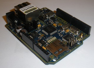
I opted for a Freetronics pack containing an EtherTen, an LCD shield, and a terminal shield:

Ikea Hacks for Organising Test Leads

My electronics workspace routinely goes from order to chaos and back again. Here are some recent Ikea hacks to help restore order…

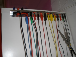
A test lead holder composed of an aluminium door handle from Ikea with banana sockets mounted every 2cm along its length. Some sockets are the recessed kind, to suit shrouded socket multimeter leads:

Open 7400 Logic Competition Entry: (Wheely) Bin Night Reminder

This is my entry in the Open 7400 Logic Competition. It’s a (wheely) bin night reminder. Because the competition was so open ended in its brief, I placed two constraints on myself:

First, I had to make do with the logic chips (and other components) I had on hand. No going to Jaycar or placing an order through Element 14; only junkbox parts allowed. I had more 4000-series parts than 7400-series parts, so the design is based on 4000 CMOS logic. Because of this constraint, it is sub-optimal in many ways - requiring more parts than had I had access to the more highly integrated CMOS parts.

Second, I had to make something that solved a problem I faced. I always forget to take the bins out on bin night. What I needed was a system of reminders. Sure, I could have set an alarm on my phone. But what would be the fun in that. So I set about designing the logic system required to remind me that:

  • The Red (garbage) and Yellow (recycling) wheely bins go out weekly on a Monday night.

  • The Green (green waste) wheely bin goes out on a Tuesday night on alternate weeks.

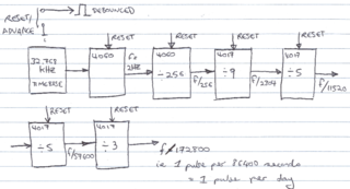
Here’s the design I came up with (it can be adapted easily to cater to different bin collection nights or other weekly or fortnightly events):

Sensible Inkscape Defaults for Use With Ponoko Templates

In the seemingly endless quest to find nice enclosures for my nixie clocks, I’ve recently cultivated an interest in the 2D laser cutting services offered by Ponoko. What could be nicer than a fully custom enclosure?

Ponoko have neato templates for laying out your design in Corel Draw, Adobe Illustrator and Inkscape. Inkscape carried the most attractive price tag, so I decided to use it.

I installed Inkscape and started playing. I found that it was doing funny things. I’d type in precise coordinates, widths and heights but they didn’t seem to ‘stick’. They’d change a little. Then I’d change the stroke width and the width and height of my object would also change. Similarly, I’d change the width and height of my object and the stroke width would change. This seemed like really odd behaviour.

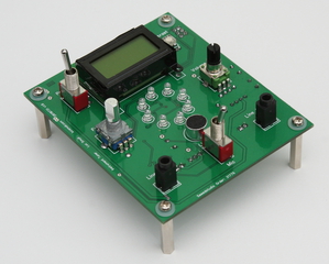
Stroboscopic Musical Instrument Tuner - Photos

My co-worker Johan - an avid photographer - kindly offered to take some photos of my latest electronics project. Here are the very impressive results of the photo shoot.

I hope to post some more details about this project here soon. It was based to a significant extent on Jim Rowe’s excellent PIC-Based Musical Tuning Aid published in Silicon Chip Magazine back in 2008.

Enjoy the photos!

Using the SN75468 as a Nixie Tube Driver

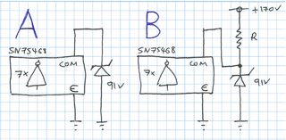
I’ve been doing some research about using the SN75468 as a Nixie tube driver. What most people who have used this arrangement note is that the ic’s common pin should be tied to a clamping voltage below the ic’s darlington transistor voltage rating of 100V.

What I’m not sure about is which of the two following clamping arrangements is the right one to use - A or B?

MSP430 LaunchPad Clock

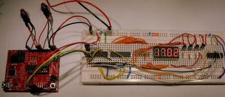
I’ve had a few MSP430 LaunchPad boards on my desk for ages and thought it was time to have a go at programming them. I like making clocks and the LaunchPad came with a nice 32.768kHz crystal that would make a stable timebase, so I set about making one.

As usual, I’ve made the schematic diagram available (see below), in case you want to build one yourself. I’ve also put the code up on GitHub so that you can compile and flash the firmware (and hopefully fork the repository and adapt it to your needs).

A Simple Amplifier for Testing Audio Circuits

I am working on a stroboscopic musical instrument tuner at the moment. Once done it will let me tune my guitar, amongst other things. It will also generate a crude sine wave and play it through a small speaker, so that I can learn to tune by ear.

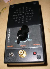
Working on this project made me realise that I was missing a handy piece of test equipment: a small, self-contained, low-power amplifier. I had bigger, more powerful amplifiers at hand, but what would be really neat is a compact, no fuss unit that I could use for testing audio circuits. So I set about making one.