This post describes my entry in the 555 contest. I was poring over the various configurations of the 555 - astable, monostable, delays, inverters, bi-stables, PWM circuits, etc. - and got to thinking whether the 555 (or many 555s!) could be used to generate an asynchronous serial bit stream.
The brief was to create a circuit with 555s as the only active components that would endlessly put out the character “5” as a valid asynchronous serial stream at 9600 bps with 8 data bits, no parity, and one stop bit (8N1). Optionally, the circuit could support sending characters other than the ever so apt character “5”. This is what I came up with:
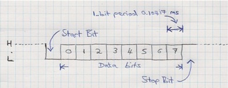
Briefly, asynchronous serial communication idles high. When a data byte is to be sent, the transmitter first holds the line low for one bit-period. This is the start bit. The eight data bits are then sent, least-significant bit first, with each bit occupying one bit-period. Finally, the stop bit is sent, which holds the line high for one bit-period and leaves it high until it’s time to send the next data byte. The bit-period I refer to is simply the inverse of the bit rate, i.e:
1/9600 = 0.00010417 seconds = 0.10417 milliseconds
Here’s a diagram showing a single asynchronous serial data frame at 9600 bps:
The ASCII value for the character “5” is 35 hex (53 decimal, 00110101 binary). The least significant bit is sent out first, so the data bits go out as 10101100. So the transmission of the character “5” will look like this:
Implementation
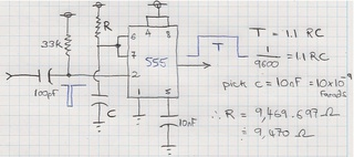
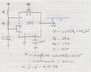
Given that the most fundamental timing element of the serial transmission is the bit-period, I began looking at ways of producing a pulse one bit-period wide. Looking at the various modes of operation of the 555, the monostable configuration seemed well suited. It is triggered by a negative going pulse and produces a positive pulse of a fixed length determined by the value of a single capacitor and a single resistor:
9.470k is not a standard resistor value, but we can parallel two standard resistors to get this value:
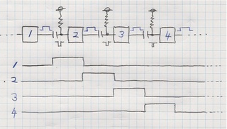
Because a single monostable can only generate one bit-period, 10 are needed to transmit an entire data byte: eight data bits + one start bit + one stop bit. Luckily monostables can be chained, such that one triggers another:
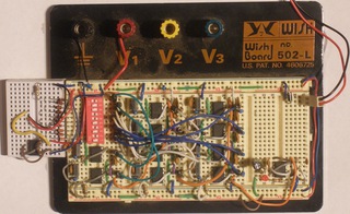
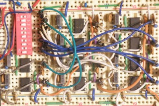
When assembled on a breadboard, the chain of ten monostables looks like this:
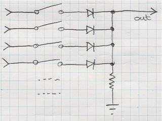
We now have a chain of monostables, wired such that the output of each goes high for one bit-period in sequence. What’s required is some way to convert these ten outputs into a single output representing a serial bit stream. In order to do this, we simply OR the monostable outputs together. This can be done with a bunch of diodes and a resistor. A bunch of switches can be thrown into the mix in order to set the right logic levels for each bit-period (in order to generate a bit sequence representing a valid character).
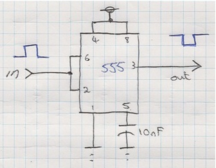
An inverter (built around a 555, of course) is required on the output of the OR gate in order to generate a true TTL asynchronous serial bit-stream - i.e. one that idles high:
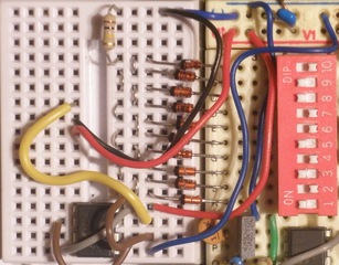
Here’s what the breadboarded “switch - diode OR gate - inverter” looks like:
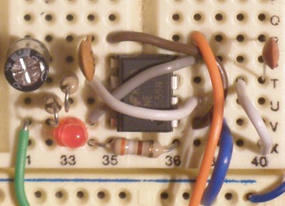
Finally, a square wave generator is required to repetitively trigger the first of the monostables in the chain. For this we use another 555, configured as an astable with a large duty, i.e. short off time:
And here is the astable on a breadboard:
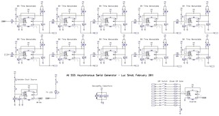
The complete circuit diagram
The complete circuit uses no less than 12 555 timer ICs to achieve its task. You can download the PDF version for easy zooming and printing:
All 555 Asynchronous Serial Generator Schematic
Does it work?
Of course! Take a look at this video of the circuit driving an old Unisys terminal (via a MAX232 chip to convert the true TTL output of the circuit to proper RS232 line levels):
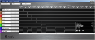
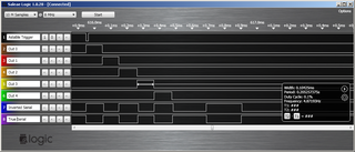
Here’s a grab of the circuit in action as recorded using a Logic logic analyser. Channel 1 shows the pulse from the astable that kicks off the process. Channels 2-6 show the staggered outputs of the first 5 of the monostables. (There aren’t enough channels on the logic analyser to show the outputs of all 10 monostables). Channel 7 shows the serial output at the output of the diode OR gate. And channel 8 shows the final true TTL serial output after the inverter:
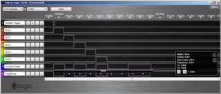
The screen grab below shows the period of a single bit: 0.10425ms. Compare this to the ideal value of 0.10417ms - not bad at all!
As can be seen in the screen grab below, the Logic’s asynchronous serial analyser interprets the transmitted character as 35 hex, i.e. the character “5”, as we’d expect. Check out the little dots that indicate the sampling points of Logic’s asynchronous serial analyser. As can be seen, they fall right in the middle of the bit-periods, suggesting that the monostables are accurately generating the required bit-period:
By flicking the DIP switches it’s possible to change the character sent - but it wouldn’t be in the spirit of this tribute to the 555 to generate characters other than “5”!
Conclusion
This project was a fun challenge. The 555 contest encouraged me to take a fresh look at a classic IC that I’ve taken for granted and overlooked. I now understand its operation much better.
My circuit uses three of the many possible configurations of the 555:
the monostable x 10
the astable x 1
the buffering inverter x 1
The project serves a marginally useful function - it’s a handy tester for asynchronous terminals. But it is a great way to learn about 555 and about the serial transmission protocol.
Where to next?
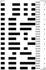
Had I had a little more time I would have liked to try to get the project to read an encoded message and spit it out as a serial bit stream. The thought I had was to print the message (below left) out on paper (where a black square is binary 1 and a white square is binary 0).
Reflective optical sensors such as the QRD1114 could be used to read in the data. These, with a bit of interface circuitry (a few more 555s anyone?), could take the place of the manual DIP switches.
The left-most column is a clocking line. This was intended to take the place of the astable in triggering the composition of a serial data frame. The remaining eight columns are the data to generate the desired character.
(BTW - I used a ruby script and Excel’s conditional formatting to generate this message. As a technique it worked quite well.)
If I find a little time in the future, I just might give this idea a go.
Credits
Credits go to:
Stuart Allen (of JACL fame) for lugging his Unisys terminal into work on a crowded intercity train during peak hour. He even changed trains at some point.
Terry Dawson (and indeed Stuart, too) for providing inspiration for where the project could be taken.
Forest M Mims III and Colin Mitchell for the handwritten notebooks they published on graph paper. A great idea that I’ve latched onto here.
…oh, and Hans R. Camenzind for inventing the 555!
