I wanted a robust enclosure for my Orange Pi Zero, so it could be placed outside and withstand at least a bit of dust and a little rain from time to time. It had to expose a power connection and a USB port and have good wifi reception. The principle use case was as a headless Linux box to run dump1090 so I could track aircraft using an attached USB DVB-T dongle.
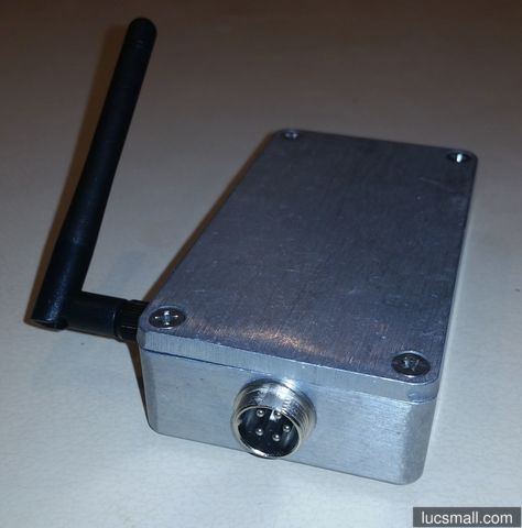
Here is what I came up with:
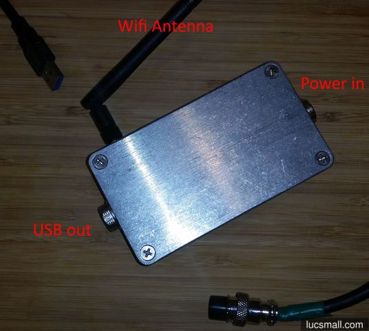
The Orange Pi Zero is housed in a diecast aluminium enclosure. Power is provided by a 2-pin GX16 connector at one end, while USB signals are carried over a 5-pin GX16 connector at the other end. I like the GX16 connectors since they are fairly easy to solder, very mechanically robust, and have an old-world aesthetic. Wifi is brought out to an external antenna not unlike one found on the back of a wifi router. All in all, this setup feels pretty solid.
Read on if you’d like further details, including a bill of materials, a connection diagram and a drilling template.
If you’re more interested in the software side of things, I have a complete tutorial about configuring the Orange Pi Zero for tracking aircraft and a basic guide to getting started with the Orange Pi Zero you might like to read.
Bill of Materials
I used the following materials for this project:
- an Orange Pi Zero.
- a diecast aluminium enclosure 115x65x30mm Jaycar HB5036
- a 14x14mm heatsink and heatsink plaster
- a 2-pin GX16 socket (sometimes called “microphone” or “aviation” sockets).
- a 5-pin GX16 socket (sometimes called “microphone” or “aviation” sockets).
- a white and a green “dupont” jumper wire
- 2 x wires with 2-pin “JST” plugs
- An eyelet solder lug and spare wire
- a wifi antenna with attached coax and a U.FL plug
- 4 stand offs, M3 bolts and nuts
- heatshrink
Adding a heatsink
The H2+ chip on the Orange Pi Zero can run pretty warm in operation, so a heatsink is not a bad idea. The chip measures 14mm x 14mm so I hopped onto Aliexpress and ordered some heatsinks to suit.
I glued the heatsink to the H2+ chip using “heatsink plaster”. This is a thermally conductive rubbery substance that eventually hardens (it took like 24 hours to set). An alternative option is to use thermally conductive double sided adhesive tape. Whatever option you choose, this is more easily done before the Orange Pi Zero is mounted in the case.
Drilling the case
Next I drilled the case. First, four M3 holes in the base of the case to mount the Orange Pi Zero. Then a 16mm hole at each end for the two GX16 sockets. Then a smaller hole on one side for the wifi antenna reverse SMA connector.
I created the following templates to assist with drilling. Feel free to download, print, and use them:
Wiring it up
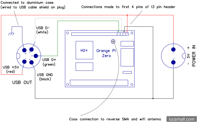
I wired up the Orange Pi Zero to the connectors according to the following diagram:
A PDF version of this diagram is also available for download.
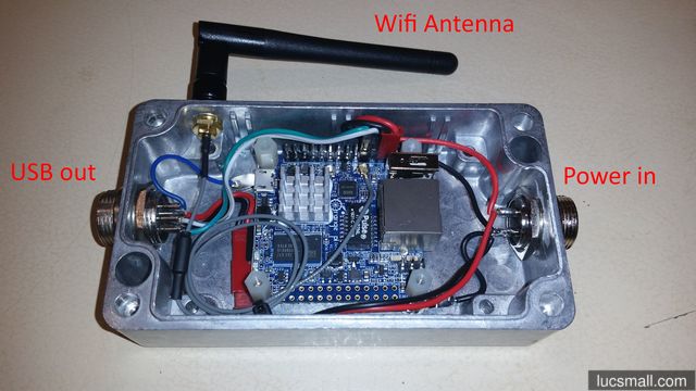
With the lid off you can see how I used JST connectors and “dupont” connectors to make connections to the Orange Pi Zero’s 13 pin header:
Putting it to use
In order to use the ruggedised Orange Pi Zero, I had to create two cables. One was fitted with a 2-pin GX16 plug to supply power to the unit. The other was a USB cable with a type-A socket at one end and a 5-pin GX16 plug at the other.
I wasn’t certain that the integrity of the USB signals would be maintained over the 5-pin GX16 connector, but so far I haven’t noticed any issues in use.
Improvements
As always, I can think of some improvements:
- Even with the heatsink, the H2+ chip still runs really hot, particularly if the ruggedised Orange Pi Zero is located outside in the searing Canberra summer heat. With an ambient temperature of 33°C the H2+ reaches about 71°C even with the heatsink. The ideal arrangement would be coupling the H2+ to the aluminium case using a conduit with low thermal resistance (like a heat pipe). But this is not trivial given the layout of the Orange Pi Zero board. Another option is adding a fan, to the detriment of ingress protection from dust and water.
- Break out 2 USB ports using a 6-pin (VCC, D1+, D1-, D2+, D2-, GND) or 8-pin (VCC, D1+, D1-, GND, VCC, D2+, D2-, GND) GX16 connector. This would allow for a bit more versatility in the use of the unit. The 13-pin header on the Orange Pi Zero exposes a second USB port so, in theory, this would be easy to do.
But for now, the current design works for it’s intended purpose - as a rugged computer for decoding ADS-B signals from aircraft.


