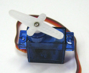
I needed a simple circuit to test an SG90 servo I purchased from DealExtreme. This was the first time I’d experimented with a servo.
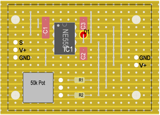
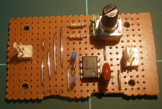
I found this servo driver circuit and decided to lay it out on perfboard (aka stripboard, veroboard, etc.):
I thought I’d post the layout in case anyone else wanted to build it up. I produced the layout in LochMaster, a stripboard layout program that has some nice features.
The following PDF file can be printed and used as a guide for breaking tracks and laying out the parts:
The two larger images show the component side of the board in colour and black and white (depending on your printer one might print clearer than the other).
The two small images show the board as viewed from the underside. This is handy for breaking tracks (which I generally do with a 3mm drill bit).
Notes on the circuit and layout:
The part designators (R1, R2, C1, C2…) follow those on the original circuit diagram.
C3 is a 100nF capacitor I added to the circuit to decouple the power supply.
D1’s cathode (the end with the band) connects to pin 6 of IC1.
Power is supplied to circuit by the 2 pin terminal to the right.
The servo is connected to the circuit by the 3 pin terminal to the left.
On the servo above:
Brown = Ground (GND)
Red = Power (V+)
Yellow = Control Signal (s)
V+ should be about +5V.
The PCB mount 50k potentiometer was sourced from Altronics.
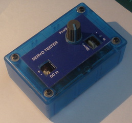
Here’s a photo of the completed project - a handy piece of kit to have around:


