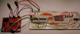
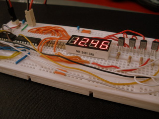
I’ve had a few MSP430 LaunchPad boards on my desk for ages and thought it was time to have a go at programming them. I like making clocks and the LaunchPad came with a nice 32.768kHz crystal that would make a stable timebase, so I set about making one.
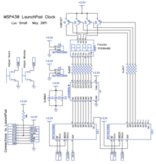
As usual, I’ve made the schematic diagram available (see below), in case you want to build one yourself. I’ve also put the code up on GitHub so that you can compile and flash the firmware (and hopefully fork the repository and adapt it to your needs).
The clock uses the MSP430G2231IN14 - the more capable of the two devices that come with the LaunchPad. I can’t think of any reason why the MSP430G2211IN14 wouldn’t work in this application, but I used the more capable chip to leave more options available for experimentation.
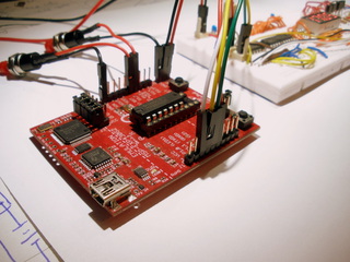
The 32.768kHz crystal is soldered to the LaunchPad board to provide the aforementioned timebase. I really like the crystal TI bundled with the LaunchPad, it has a real feeling of quality about it.
Jumper wires hook the relevant ports and power connections from the LaunchPad to the circuit constructed on the breadboard. Two switches are connected by jumper wires to facilitate setting the hours and minutes.
The display, a four digit common anode 7-segment display from Futurlec, is driven in a multiplexed fashion. The drive circuit is perhaps a bit over-engineered. It could drive bigger displays at much higher currents. It consists of two 74HC595 shift registers, which act as port expanders, allowing the 8 cathodes and 4 anodes of the display to be driven by just four MSP430 pins.
The display’s cathodes are driven by a ULN2803 octal darlington transistor array. It has integrated base resistors, so it’s safe to connect its inputs directly to the 74HC595’s outputs. The eight 82 ohm resistors limit the current going to the display. Four BC327 PNP transistors drive the anodes of the display. Being discrete devices, these require base resistors.
The code does a few things:
Outputs ACLK on P1.0. This is handy for verifying that ACLK is being sourced from the 32.768kHz crystal. Just put a frequency counter on this pin and it should read 32.768kHz.
Uses the Watch Dog Timer (WDT) as an interval timer. It’s set to fire an interrupt 512 times a second. The interrupt does two things:
First, the it updates the “seconds” value of the code that maintains the real time clock once every 512 times it fires (e.g at 1Hz).
Second, it polls the state of the switches and runs some debouncing code.
The main loop checks the debounced state of the switches and updates the “hour” and “minute” counters respectively.
It then takes care of updating the multiplexed display by writing out to the 74HC595 shift registers.
The clock has a fairly minimal feature set:
At power on, it flashes to indicate the time is not set.
The time is shown in 24-hour format.
Buttons allow setting the hour and minute to be incremented.
When the minute button is pressed, the seconds counter is reset to zero to allow fairly accurate synchronisation of the clock to another source.
When the hour button is pressed, the seconds counter is unaffected. This is handy for daylight savings changes, where you want the second to be preserved.
Resources:
Download the MSP430 LaunchPad Clock Circuit diagram as a PDF for easy zooming and printing.
The source code for the firmware on GitHub.


