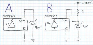
I’ve been doing some research about using the SN75468 as a Nixie tube driver. What most people who have used this arrangement note is that the ic’s common pin should be tied to a clamping voltage below the ic’s darlington transistor voltage rating of 100V.
What I’m not sure about is which of the two following clamping arrangements is the right one to use - A or B?
I’ve seen evidence of both in use - presumably with success in either case:
A - the yet another nixie clock
B - the Nixie Watch
I’d think that option A would suffice, because the nixie tube will generate the voltage that needs to be clamped, but I’m just guessing. Does anyone have an answer?
Update:
I posted this query to the neonixie-l group. And received a very helpful response from David Forbes:
Circuit B guarantees that the other cathodes are pulled up to 91V by the
clamp diodes in the driver chip.

Circuit A depends on stray current flowing from the anode to the unlit
cathodes to energize the Zener diode. This current may be very small, in
the microampere region, since these cathodes are unlit. The Zener diode
therefore may be operating at a much lower voltage than 91V, resulting
in white dots or other unwanted artifacts. Depends on the Zener diode,
of course.

Short answer: B is guaranteed to work, A is try-it-and-see.
I’ll be experimenting with Circuit B when I next get the chance. Thanks again, David.
