This post documents my build of the 8 transistor AM superhetrodyne receiver featured in Ronald Quan’s excellent book Build Your Own Transistor Radios. In reality, my version is a 4 transistor radio since I’ve used an audio amplifier chip in place of the 4 transistor amplifer used in the original design. The main reason for the change was that I did not have the audio transformers required for the original design on hand.
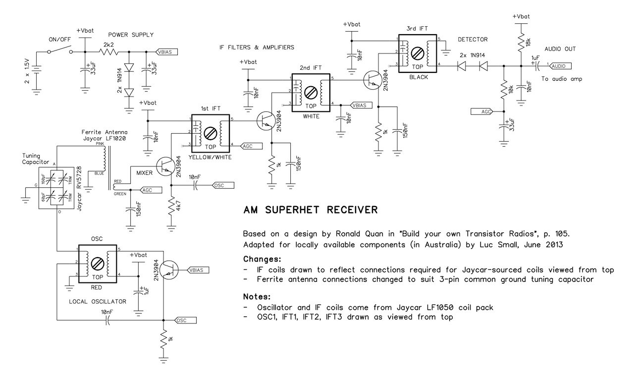
The radio is built entirely out out parts from my junkbox and a ferrite antenna LF1020, tuning capacitor (polyvaricon) RV5728, and oscillator and IF coils LF1050 from Jaycar. This post is aimed at those who want to build the receiver using these easily obtainable parts in Australia. I have drawn up a schematic with the circuit changes required to make the receiver work with these parts. The changes are required because the tuning capacitor gangs share a common ground and because the pinouts of the oscillator and IF coils differ to those specified in the design.
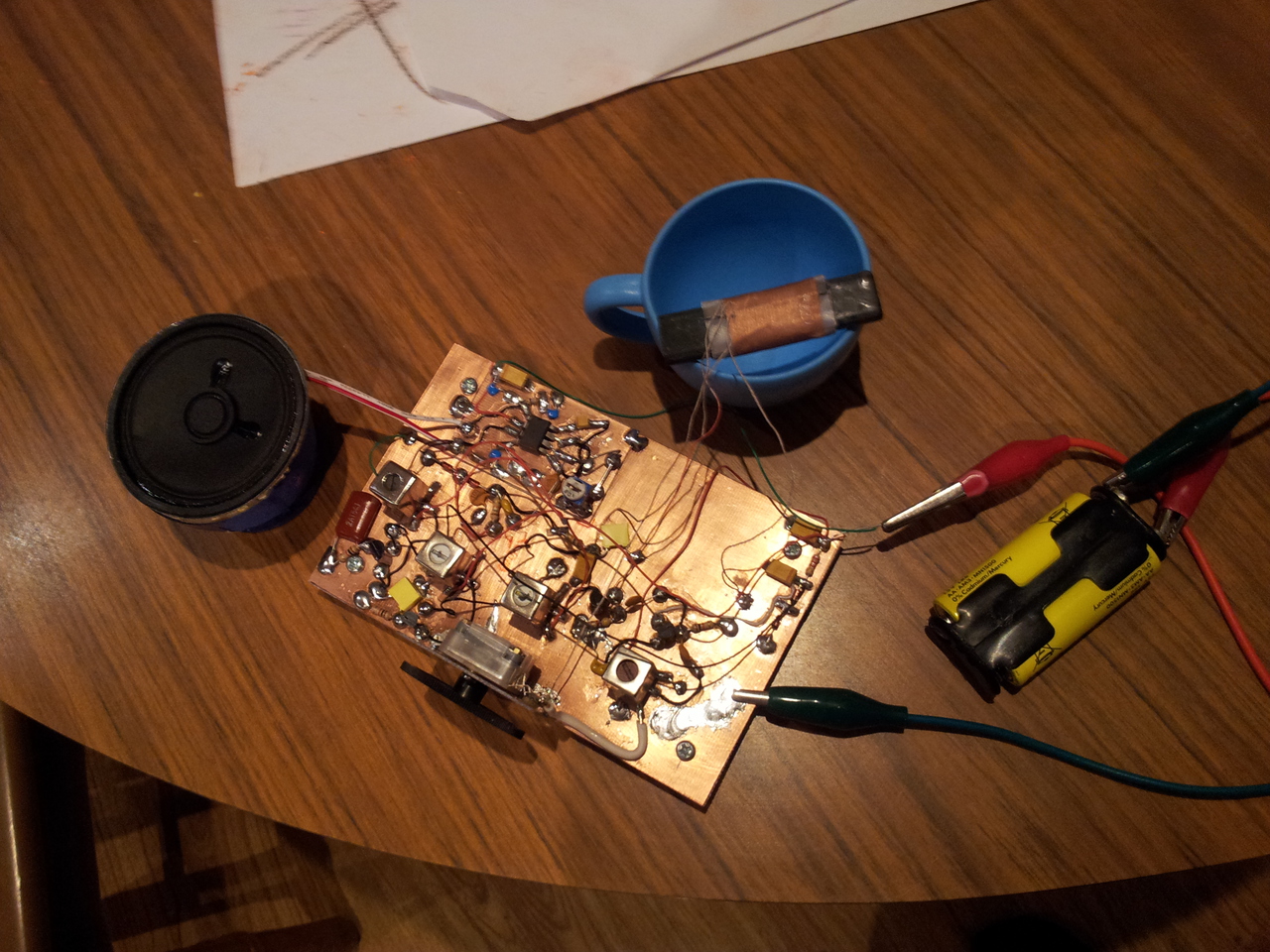
The radio works a treat. It pulls all the local stations at good volume and with good quality. The selectivity is excellent, as you’d expect from a superhet. I’ve peaked the IF stages but haven’t yet aligned the local oscillator and tuning. So it may be that the sensitivity can be improved even further. I really enjoy listening to this set.
Local Oscillator
It seemed logical to start by constructing the local oscillator since it can be tested in isolation. The bias voltage circuit required by the oscillator and other sections was also built.
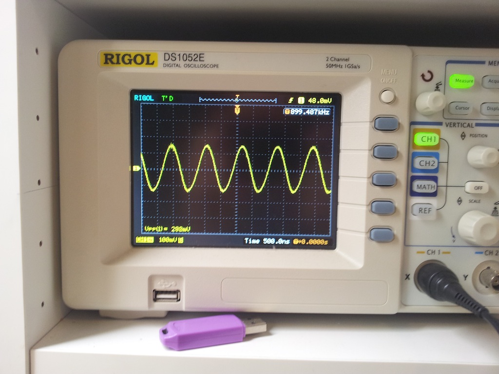
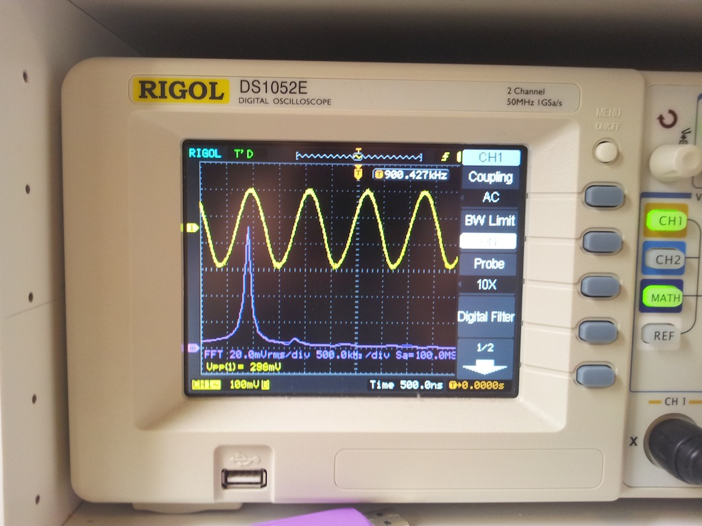
After swapping connections on the oscillator can, the oscillator leapt into life. With the tuning capacitor at maximum capacitance it oscillates at ~900kHz and at minimum capacitance at about ~2MHz. This gives an 1100kHz tuning range from 445kHz to about 1545kHz (using a 455kHz IF frequency). By contrast the AM band extends from 531 to 1611 kHz, a spread of 1080kHz.
So range of tuning is just about perfect, but to be properly aligned the oscillator should adjusted for about 986kHz at the bottom end of the tuning range. The tuning range can be adjusted by turning the slug on the oscillator can or by adjusting the “oscillator” trimmer on the back of the tuning capacitor.
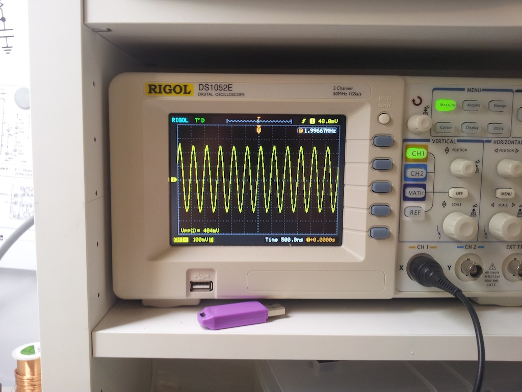
The sine wave output looks pretty pure according to the spectrum analyser function on the DS1052E:
The Rest of the Build
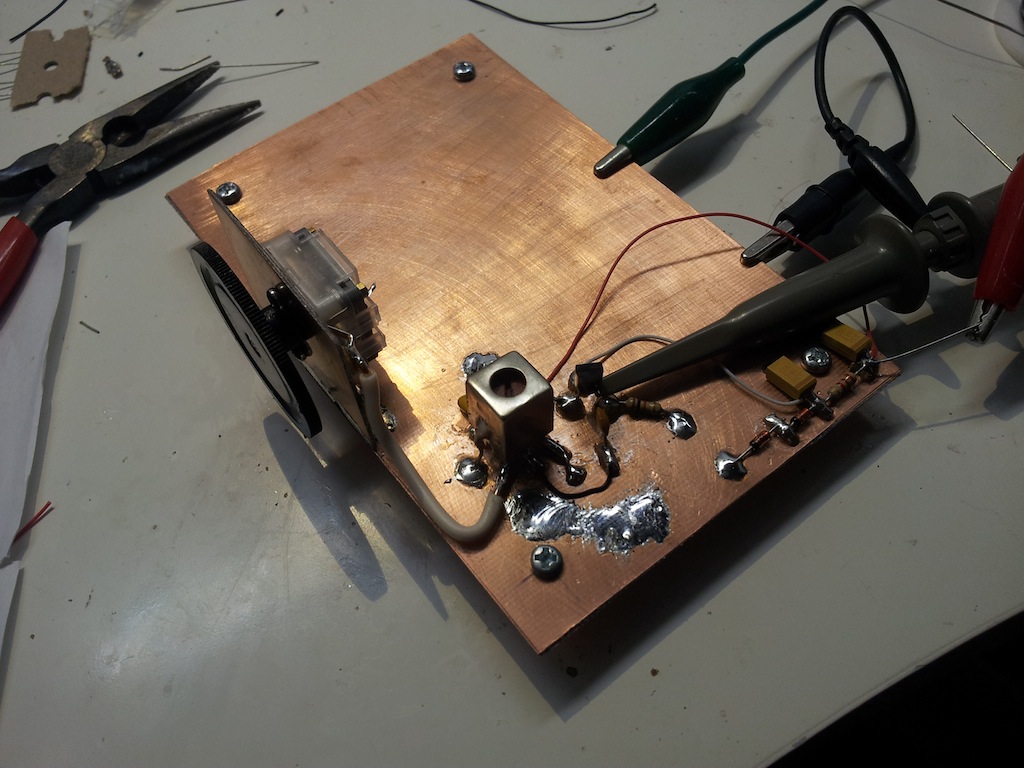
Everything else was built next. I couldn’t see any other way but to bite the bullet and complete the build. I guess the intermediate frequency filters and amplifiers could have been built standalone and tested with 455kHz signal source. But building the mixer and wiring up the tuned circuit was very little extra work.
The IF cans are a bit of a mystery to me and scant data is provided with them. Some connections are unambiguous, such as the centre tap on the coils, but others were not obvious. So I made the connecting wires longer than usual to allow them to be swapped if the circuit didn’t work in the initial configuration. This proved a wise move.
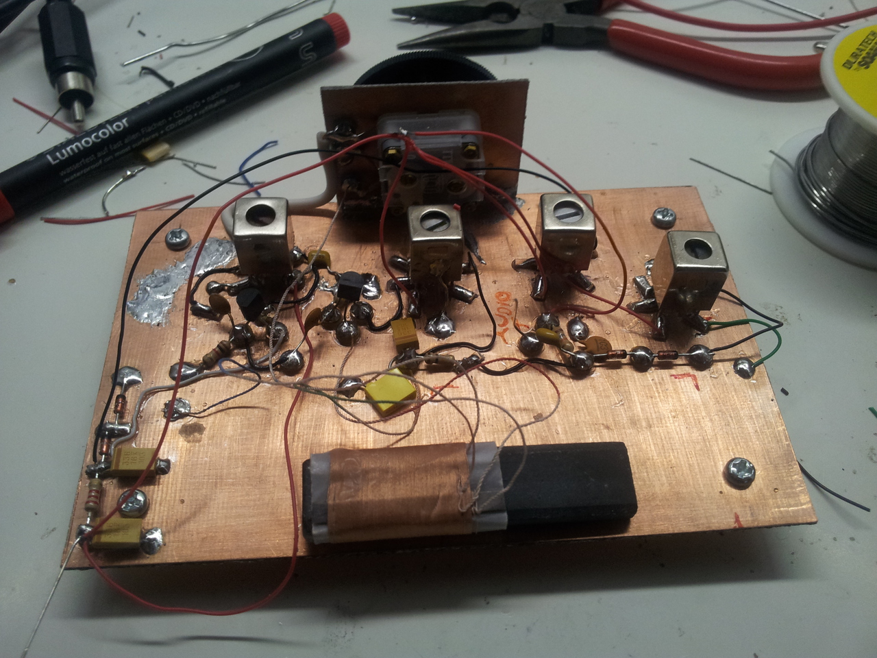
Before construction, the IF cans were peaked for 455kHz in a fairly unconventional manner. I built this wideband oscillator circuit on a scrap of PCB material. In turn I connected the two outer pins of the 3-pin side of the IF coils to the oscillator. I connected the output of the oscillator to my scope and enabled the frequency counter function. I adjusted the slug in each IF coil until the frequency counter reported close to 455kHz. I had no idea if this would actually work since I thought that additional capacitances in-circuit could pull the resonant frequency a bit (or a lot). But in practice my IF coils barely required adjustment after the circuit was completed.
Because the gangs of the polyvaricon tuning capacitor are connected to form a common ground (the centre connection) I had to deviate from the published circuit which had the ferrite core configured as an auto transformer. Had I used this, the AGC bias to the base of the mixer transistor would have been shorted to ground. So rather than connecting the ferrite coils together to form a tap, I’ve used them in isolation, with the smaller coil (distinguished by red and green wires) coupling the RF energy to the mixer and allowing the bias voltage to be applied. I haven’t encountered any issues with this modification.
Download a PDF version of the schematic or click the image below to see a full-sized JPEG version: