This is a bit of a retrospective on things I’ve learned since I built my first nixie clock back in 2007. Its been suffering from what looked like cathode poisoning for a while, so I discontinued its use and decided to upgrade it.
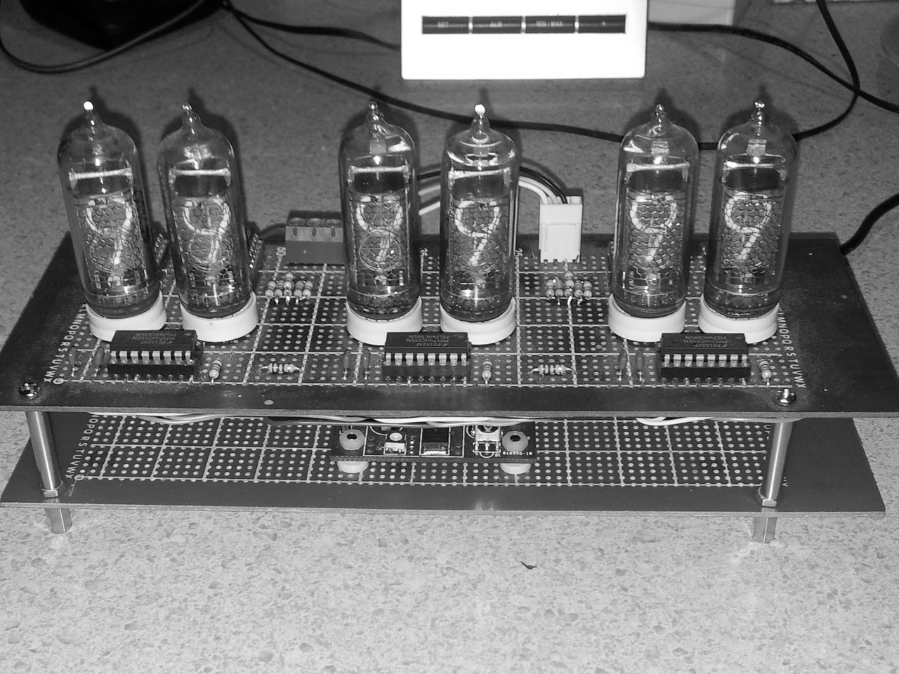
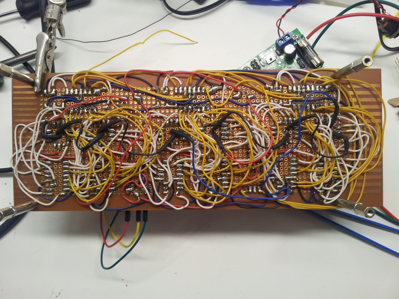
First let’s look at the specs. It’s built using point-to-point wiring on two stacked boards. The top board consists of 6 Russian IN-14 nixie tubes. These are driven by 6 Russian KM155ID1 equivalents to the 74141 nixie decoder/driver, driven in turn by 3 74HC595 latching shift registers. The top board also includes six LEDs that provide blue uplighting of the nixie tubes.
The lower board contains a 5V linear regulator (a 7805), a high voltage power supply built around an NE555, a Picaxe 18X MCU, a DS1307 real time clock, some switches and a MOSFET to drive the LEDs with a PWM signal.
The feature set is limited:
- time display
- time setting using buttons; one for hours and one for minutes. (These were added later; for the first couple of years the time had to be set by updating the firmware - poor form, I know!)
- battery backup of the time
- 5 levels + off of diming on the blue LEDs. (As a bonus, sometimes the dimming would go crazy for reasons never determined. Bad software or switch debouncing logic no doubt)
In Retrospect
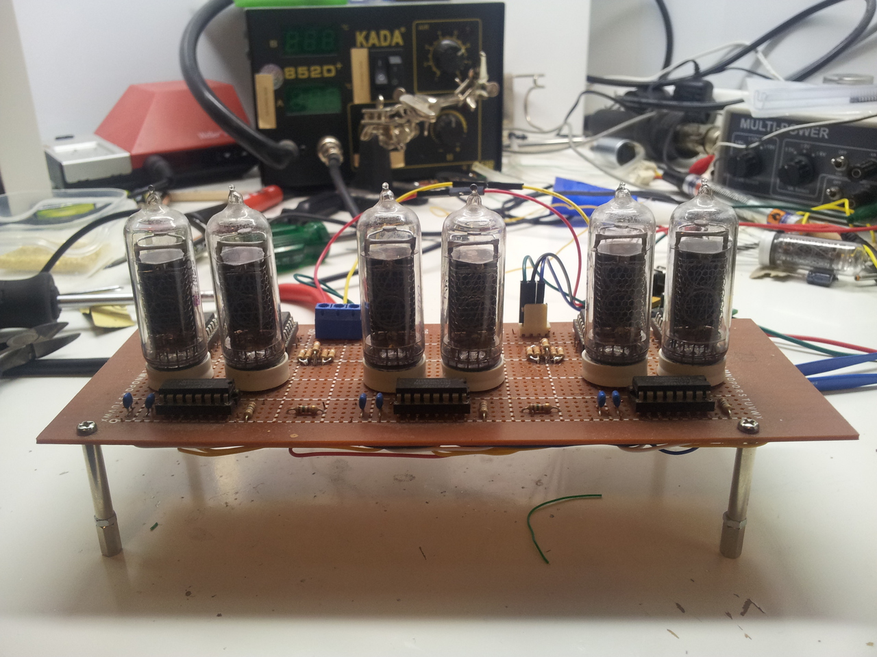
The top board is actually still entirely usable - the combination of the KM155ID1 and the 74HC595 is very practical and reliable. My original choice of 33K anode resistors was off the mark. I’ve paralleled some 39K resistors to reduce the anode resistance to 18K. This provides about 2mA (measured) of current per tube at 170V. This is a tad below the IN-14’s maximum rated current of 2.5mA but should be high enough to prevent cathode poisoning. If I start seeing signs of poisoning, I can always up the anode voltage to 180V to bring the current up a bit. The blue LEDs are all well and good, but they are such a cliche of modern electronics that I prefer not to use them these days.
The bottom board is more problematic and I’ve decided to retire it:
- Being a linear regulator, the 7805 gets quite hot dropping the 12V from the plug pack. It turns out that the KM155ID1 chips are quite power hungry (like all TTL chips, I guess), placing a reasonable load on the regulator.
- The NE555 high voltage power supply, based on a common circuit, starts to droop at even modest currents. It simply is not up to supplying 6 x 2mA = 12mA to the nixies. This may well be due to the inductor, diode, MOSFET, output capacitor and layout used in my implementation, however with an NE555 at its core this boost regulator was never going to be a stellar performer. (Don’t get me wrong, I’m in awe of the 555’s versatility; it just ain’t gonna beat a purpose designed boost regulator chip).
- The RTC uses a standard tuning fork crystal and these things gain or loose time too quickly for my liking. I prefer a temperature compensated crystal oscillator (TXCO) or even a GPS module in my clocks these days. (The battery, however, is still going strong).
- The Picaxe 18X is a good chip, but its lack of proper interrupts made it hard to implement good switch debouncing. I tried using a D flip flop to capture a button press event and then allow the Picaxe to reset it after it had detected the event. This seemed like a good solution, but it didn’t occur to me that I would need to debounce the switch inputs into the D flip flops using something like a 74C14 monostable. After that realisation I dumped the idea of a hardware debounce arrangement and implemented a primitive software debounce. (The quest for proper interrupts lead me to start learning about and using AVR microcontrollers.)

The Revamp
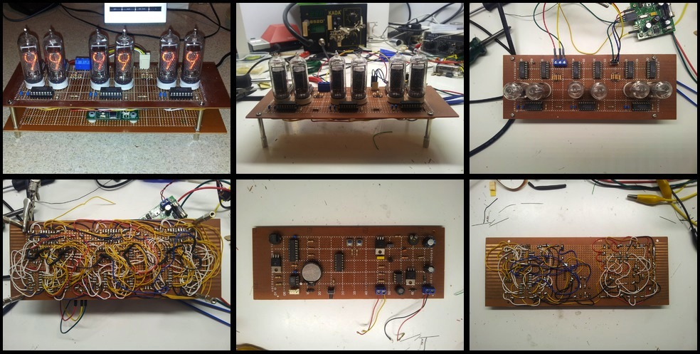
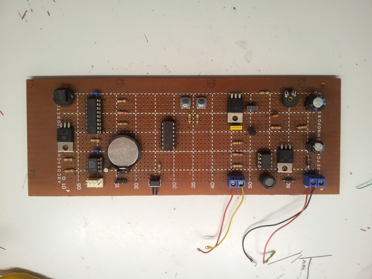
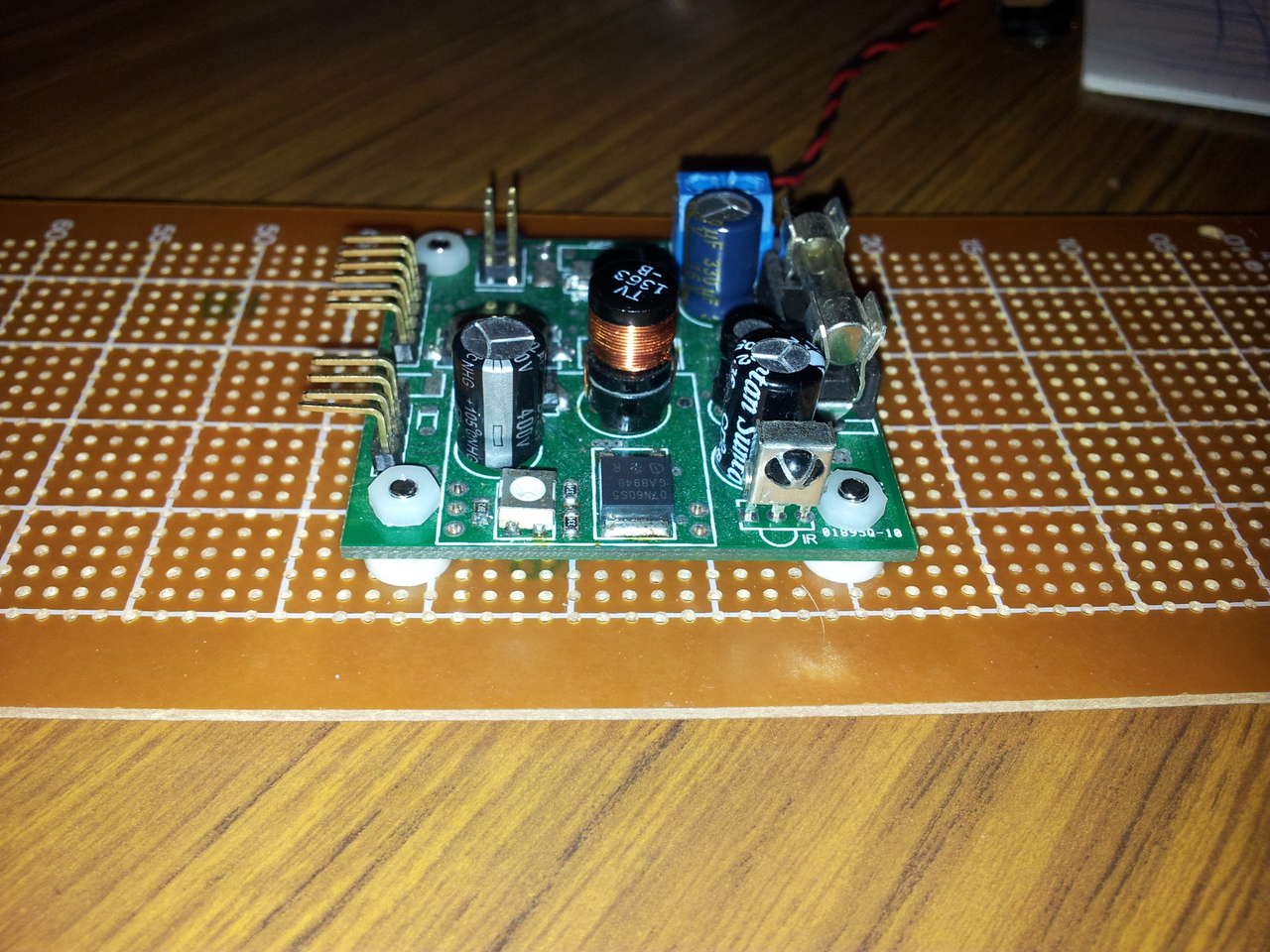
Apart from paralleling the anode resistors, the revamp consisted of swapping out the bottom board. The new board has these main components:
- a 5V buck regulator based around an MC34063 for better efficiency than a linear regulator.
- a high voltage boost regulator also based around an MC34063 that provides considerably higher output current while maintaining the set voltage (typically 170V).
- a DS3231 RTC with inbuilt TXCO and provision to connect an EM406 GPS module.
- an IR receiver module so that clock functions and time can be set by remote control.
- an ATMEGA88 AVR.
- surface mount construction to make it extremely compact. (Makes for quite a contrast with the point-to-point wiring of the top board).
The feature set is a work in progress, but so far includes:
- time display
- time setting by remote control
- “lamp test” - cycling all digits at various speeds
- count up timer
- received RC5 IR code display